
Use case
How to design optics for a handheld medical laser
Ro Bahuguna, Lead Optical Engineer, Opdo · October 14, 2026 · 6 min read
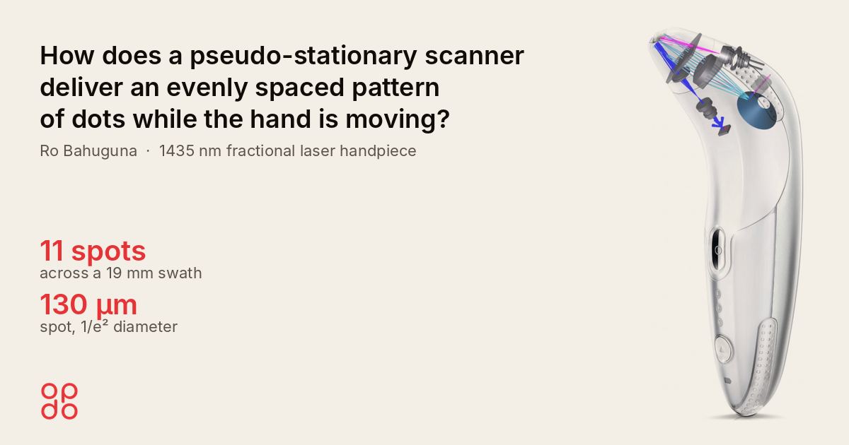
I designed the optics for a 1435 nm fractional laser handpiece that places 11 spots of 130 µm across a 19 mm swath while the hand keeps moving at 1 to 2 cm/s. An optical mouse sensor measures hand speed, and a rotating 11-facet axicon moves each spot with the hand during the pulse.
Fractional photothermolysis is a skin treatment that heats a grid of microscopic columns of tissue and leaves the skin between them untouched, so the surface re-epithelializes within about a day (Manstein et al., 2004). There is virtually no down time between treatments.
Why is hand motion a problem for a handheld laser?
A handheld laser has to keep each spot in one place for the whole pulse, and the hand holding it never stops. At 2 cm/s, the hand covers 20 µm every millisecond. Over just 5 ms that is 100 µm, most of a 130 µm spot, so without compensation the spot smears into a line.
The design had to do this at 1435 nm. Near 1450 nm, water absorbs enough to keep the heat in the upper dermis, about 150 to 400 µm below the epidermis (J. Biomed. Opt., 2003). The source is a diode with a diffraction-limited beam (M² = 1), 1.5 W at up to 70% duty cycle. It had to place 11 spots across a 19 mm swath, 1.9 mm apart, while the user moves anywhere from 1 to 2 cm/s. The hand sets that speed, not the optics.
A galvanometer scanner can place the same spots, but it only covers a fixed square before the user has to lift the device and move it to the next area. This is known as stamping. The axicon scanner paints the pattern continuously as the hand moves, so the treatment stays even.
How do you design a fractional laser handpiece?
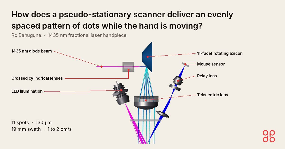
The scanner moves the beam with the hand during each pulse, so the spot stays put on the skin. Four parts make that work:
- Two orthogonal cylindrical lenses make the beam round. A diode diverges faster in one axis than the other. One cylinder collimates each axis. Because M² = 1 in both, matching the waists in size and position also matches the divergence.
- A rotating axicon, a cone-shaped reflector cut into 11 facets, steps the beam across the swath. Each facet's tilt sets its spot's position across the swath. As the axicon turns, the facet sweeps that spot in the direction of hand travel, matched to hand speed, then the next facet takes over.
- A mouse sensor closes the loop. A relay lens images the skin onto an optical mouse chip, the same sensor found in a computer mouse, while an LED lights the skin. Rollers on the tip ride on the skin. As they move across the face, the chip measures hand speed, and that speed drives the axicon's rotation.
- A toroidal telecentric lens keeps every spot consistent. The chief ray at every scan position leaves parallel to the axis, so each spot meets the skin at the same angle across the 19 mm swath. The lens is toroidal, with different power in its two axes, so the spot at the skin comes out circular.
The idea is not new to optics. Aerial film cameras faced the same problem: the aircraft moves during the exposure. Their answer was forward motion compensation. It moved the film so that "a point on the ground was being exposed onto exactly the same place on the film" (Pacey and Fricker, 2005). This scanner does the same for a hand on skin, with the beam moving instead of the film.
The design in numbers
The scanner places 11 matched 130 µm spots across 19 mm while tracking the hand anywhere from 1 to 2 cm/s.
| Metric | Value | Basis |
|---|---|---|
| Wavelength | 1435 nm | Design |
| Beam quality | M² = 1 | Diode specification |
| Output power | 1.5 W, up to 70% duty cycle (1.05 W average) | Design |
| Spot size | 130 µm (1/e² diameter) | Design |
| Spots per row | 11 | Axicon facets |
| Swath width | 19 mm | Design |
| Spot pitch | 1.9 mm | 19 mm over 10 intervals |
| Hand speed tracked | 1 to 2 cm/s | Design range |
| Hand travel per millisecond, at 2 cm/s | 20 µm | Calculated |
| Nominal irradiance (power over 1/e² area) | about 11 kW/cm² (peak about 23) | Calculated, 1.5 W over the spot area |
| Laser class | 1M at the operating duty cycle | Design analysis |
What it means for your handheld device
If a person moves your optics, treat the hand as part of the optical system. Measure its motion and let the beam follow it, rather than asking for pulses short enough to freeze it. A mouse sensor is cheap and mature, and it measures exactly what matters: how the surface moves under the device.
Which of your designs would you hand to Opdo's AI agents first?
Frequently asked questions
Why not just use shorter pulses?
A 1.5 W diode needs a pulse long enough to deliver useful energy into each spot, and at 2 cm/s the hand moves 20 µm every millisecond, so a 5 ms pulse would smear across 100 µm. Moving the beam with the hand keeps the pulse long and the spot sharp.
Why 1435 nm?
Near 1450 nm, water absorbs enough to keep the heat in the upper dermis, about 150 to 400 µm below the epidermis. That is the depth fractional resurfacing targets.
Can Opdo design the optics for our handheld device?
Yes. Bring us your use case, and Opdo's AI agents and optical engineers deliver a production-ready design, working in the tools you already use, such as Zemax, Code V and FRED.
How to start
Want to design your next handheld device with AI? Bring us your use case. We'll deliver a production-ready design. Talk to us
What would you design with AI agents?
Sources
- Manstein D, Herron GS, Sink RK, et al. "Fractional photothermolysis: a new concept for cutaneous remodeling using microscopic patterns of thermal injury." Lasers in Surgery and Medicine 34:426–38, 2004. doi:10.1002/lsm.20048
- "Subsurface skin renewal by treatment with a 1450-nm laser." Journal of Biomedical Optics 8(3), 2003. doi:10.1117/1.1586703
- Pacey R, Fricker P. "Forward Motion Compensation (FMC): Is It the Same in the Digital Imaging World?" Photogrammetric Engineering & Remote Sensing, November 2005. PDF
See how Opdo sources and verifies your parts.
One request in, a verified part out — routed to the right technology for your geometry, material, and tolerance.