
A robot's head camera has to see a whole server rack and read a 2 mm status LED on it. One camera cannot do both. This design uses two: a 127° stereo pair for depth and a 30.5° color camera that puts five pixels on a 2 mm LED at 3 m. An 850 nm dot projector cuts the stereo pair's worst depth errors by more than three times.
Angular resolution is the angle one pixel covers, and it sets the smallest thing a camera can make out at a given distance.
About this work. We set this problem ourselves, as a test of our AI agents on a brief written the way a robotics team would send it. A data hall suits a test because the scene is regular: rows of identical racks, a known aisle width, status LEDs of a known size. The numbers in the problem can be written down, so the numbers in the answer can be checked. Opdo's AI agents ran the lens design and the checks, and our engineers set the requirements and made the design calls.
Why can't one camera see the whole rack and read its LEDs?
A wide view spreads pixels thin, and a small LED far away needs them packed tight.
The robot drives down the middle of a 1.2 m aisle, so its camera sits 0.6 m from the rack face. A rack is 2.4 m tall. From half that height, the floor and the rack top are each 63.4° off axis, which makes 127° top to bottom.
A 2 mm LED at 3 m spans 0.67 milliradians. Three pixels across it means 0.22 milliradians per pixel. Spread over 127°, that is about 10,000 pixels top to bottom, or 75 to 130 megapixels per camera depending on the sensor's shape. A stereo pair needs two of them.
The sensor here has a tenth to a sixth of that. Sony's Pregius S IMX535, in color, and IMX545, in mono, are standard industrial sensors with 4128 by 3008 pixels of 2.74 µm, which is 12.4 megapixels. Their global shutter exposes every pixel at once, so a moving robot does not skew the image.
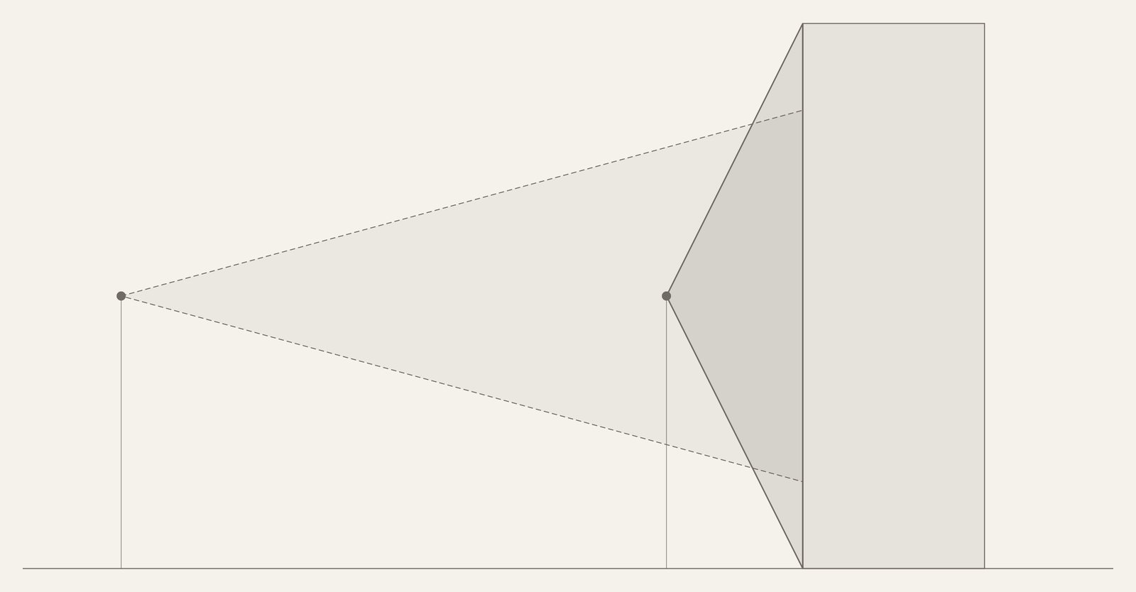
The spec for the head camera:
| Requirement | Target |
|---|---|
| View | A full rack, floor to top, 2.4 m, from the middle of a 1.2 m aisle, in one view |
| Status LEDs | 2 mm across, read at 3 m, with 5 m as the goal |
| Depth | 5 mm error at 1 m and 3% of distance out to 5 m, on glossy black bezels and mesh doors |
| Light | 0 to 500 lux, lights off included |
How do you design a robot camera for both jobs?
Split the jobs between two kinds of camera. Three parts make that work.
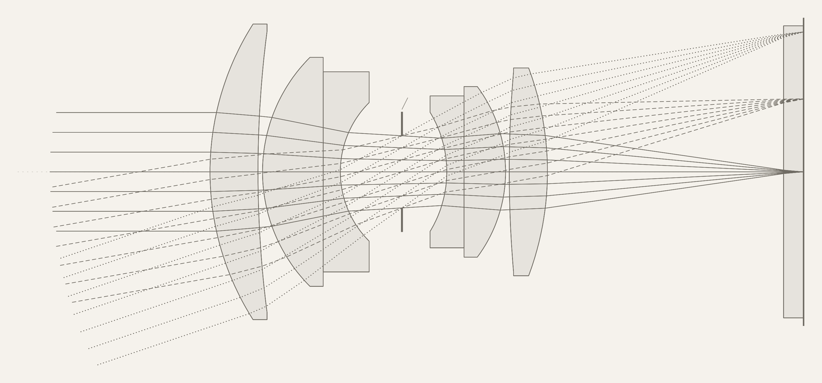
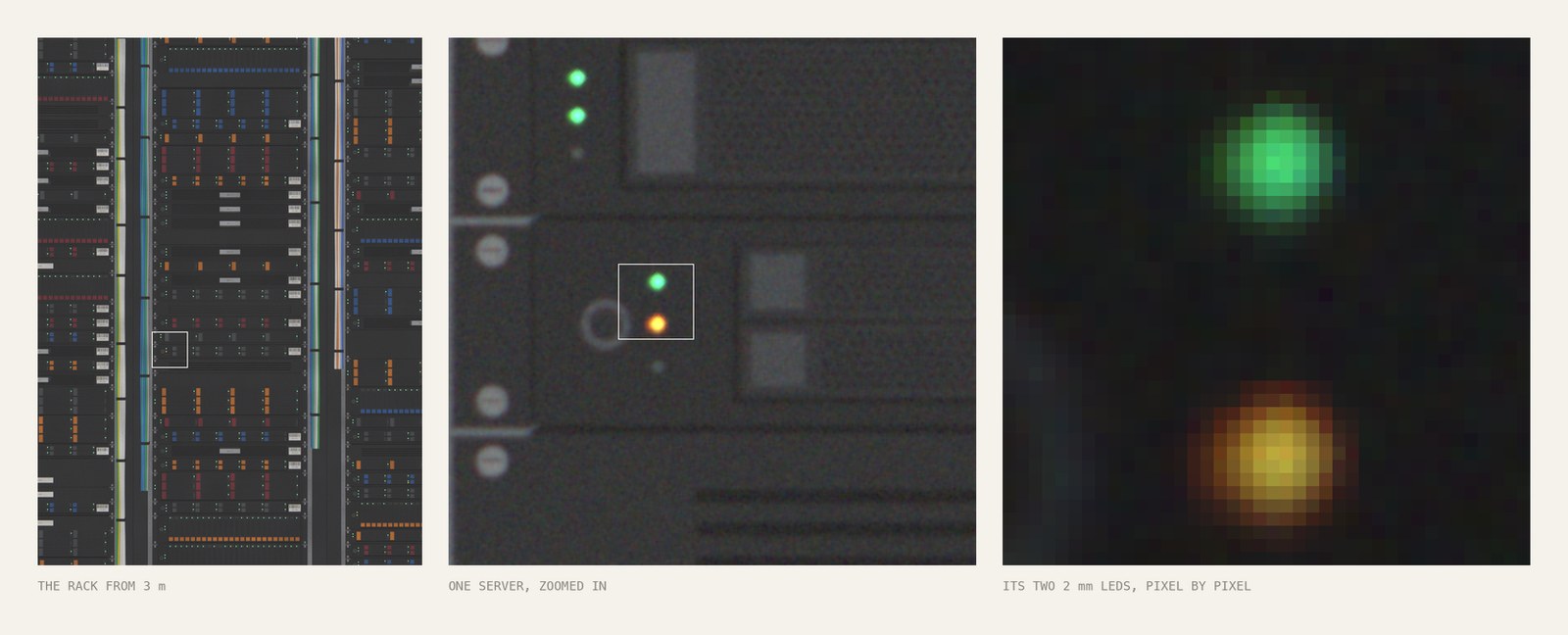
A narrow color camera reads the LEDs. A 20.75 mm, F/3.5 lens on the color sensor images a 2 mm LED at 3 m onto 13.8 µm, which is 5.05 pixels. At 5 m it is 3.03 pixels. The view is 30.5° by 22.5°, so at 3 m it covers 1.63 m of rack height and needs two tilt positions. From 5 m it sees the whole rack. The lens is a six-element double Gauss, a form camera lenses have used for more than a century (Kingslake, 1989).
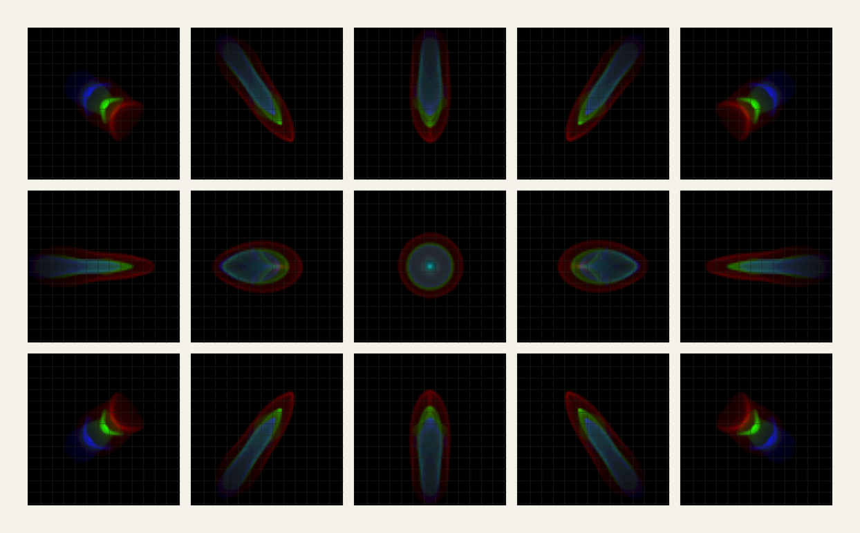
A wide stereo pair measures depth. Two 5.09 mm, F/3.5 lenses sit 100 mm apart. Depth error follows from disparity error:
A 5 mm error at 1 m allows 2.5 µm of disparity error, which is 0.93 pixels. The 3% limit at 5 m allows 1.1 pixels. The rack sits inside ±63.4°, so the pair needs depth only out to 65° off axis.
A projected dot pattern lets the pair read glossy black racks. The two cameras see the rack from slightly different places, so every label, vent and drive bay lands a few pixels apart in the two images. That shift gives the distance, which tells the robot where the rack and its parts are. Glossy black bezels and horizontal vent slats give a matcher little to compare, so an 850 nm projector on the head throws a fixed field of small dots onto the rack. It also lets the robot work with the lights off.
We rendered the pair's view of a simulated rack through the lens design, once with a plain floodlight and once with dots. We matched each pair with FoundationStereo, an open learned stereo model (Wen et al., 2025).
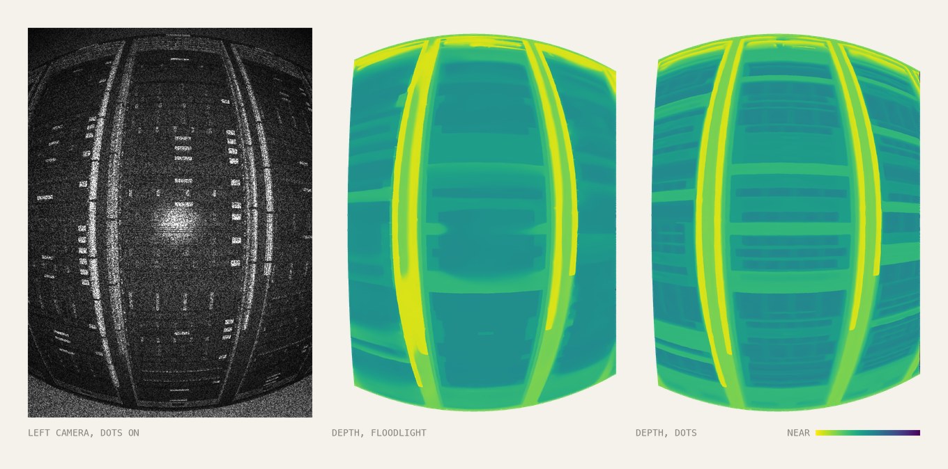
The dots cut the worst depth errors by more than three times. On the solid rack faces at 0.6 m, the 95th percentile error falls from 13.9 mm to 4.1 mm, inside the 5 mm spec:
| Light | Median error | 95th percentile error | Rack face within 5 mm |
|---|---|---|---|
| Plain floodlight | 0.7 mm | 13.9 mm | 81% |
| 850 nm dots | 0.7 mm | 4.1 mm | 96.5% |
With a floodlight, the errors sit on vent slats that run parallel to the baseline, where the two images have nothing to compare. The dots give the pair something to match everywhere. With them, the 95th percentile error stays under 4 mm out to 55° off axis and reaches 6.8 mm at the edge of the view.
The design in numbers
Two lens designs and three 12 MP sensors cover both jobs.
| Metric | Value | Basis |
|---|---|---|
| Rack view from mid-aisle | 127° top to bottom | 2 × atan(1.2 m / 0.6 m) |
| Angle of a 2 mm LED at 3 m | 0.67 mrad | 2 mm / 3 m |
| Pixels one camera would need | about 10,000 top to bottom | 127° at three pixels per LED |
| Sensor | Sony IMX535 color and IMX545 mono, 12.4 MP, 2.74 µm pixels, global shutter | Off-the-shelf part |
| Narrow lens | 20.75 mm, F/3.5 | Design |
| Pixels on a 2 mm LED | 5.05 at 3 m, 3.03 at 5 m | Calculated |
| Narrow view | 30.5° by 22.5° | Calculated |
| Wide lens | 5.09 mm, F/3.5, 850 nm | Design |
| Stereo baseline | 100 mm | Design assumption |
| Disparity error allowed | 0.93 px at 1 m, 1.1 px at 5 m | Calculated from the depth spec |
| Depth coverage | 65° off axis | Design |
| Depth light | 850 nm dot projector | Design |
| Depth error at 0.6 m | 4.1 mm at the 95th percentile (13.9 mm without dots), 96.5% of the rack face within 5 mm | Simulated |
Frequently asked questions
How many pixels does a camera need on a status LED? This design puts five pixels across a 2 mm LED at 3 m and three at 5 m. Telling red from amber and catching blink patterns on real images is still to be tested.
Does stereo work on glossy black server racks? With a plain floodlight, only partly: in our simulation 81% of the rack face came within 5 mm. It fails on vent slats that run parallel to the baseline. A projected 850 nm dot pattern brings that to 96.5%.
Can Opdo design the vision system for our robot? Yes. Bring us your use case, and Opdo's AI agents and optical engineers deliver a production-ready design, working in the tools you already use, such as Zemax, Code V and FRED.
How to start
Want to design your next camera system with AI? Bring us your use case. We'll deliver a production-ready design. Talk to us.
Related: How to design a thermal camera lens that stays in focus from -40 to +85 °C.
What would you design with AI agents?
Sources
- Szeliski R. Computer Vision: Algorithms and Applications, 2nd ed. Springer, 2022. szeliski.org/Book
- Kingslake R. A History of the Photographic Lens. Academic Press, 1989. Open Library
- Sony Pregius S IMX535 and IMX545 image sensors, distributor listing. FRAMOS
- Wen B, Trepte M, Aribido J, Kautz J, Gallo O, Birchfield S. FoundationStereo: Zero-Shot Stereo Matching. CVPR 2025. github.com/NVlabs/FoundationStereo